Geohazard Management on the Canadian National Railway Corridor
A Multi-sensor Approach
In Western Canada, substantial lengths of the transportation corridors are located within steep mountainous terrain and deeply incised river valleys. This is also the case for the Canadian National (CN) rail lines, which traverse the Rocky Mountain, Cascade and Coastal ranges from Edmonton, Alberta, to the ports of Vancouver, British Columbia (BC). Along this corridor the railway infrastructure is exposed to various slope geohazards including landslides, debris slides and rockfalls, all of which are problematic for the safe and efficient operation of the railway. In a recent case of rock slope failure along the CN rail line in British Columbia, a multi-sensor approach was undertaken to identify other potential threats in the area, to monitor stability of the rock slope during remediation work and to aid in the planning of rock scaling and blasting.
(By Ryan Kromer, Dr Jean Hutchinson, Dr Matt Lato, and Tom Edwards)
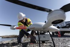
Managing the geohazard risks is challenging due to complex slope topography, limited access to remote sites, the large number of geohazard sites and the length of the corridor. Since 2012, in addition to track-level and aerial inspections, a series of high-resolution gigapixel images – from terrestrial laser scanning (TLS), aerial laser scanning (ALS), ground-based photogrammetry and oblique aerial photogrammetry (from helicopter and unmanned aerial vehicle (UAV) platforms) – has been collected at known geohazard locations. This effort is part of the Railway Ground Hazard Research Program, a collaborative project between industry, government and universities (www.carrl.ca/RGHRP) to identify and characterise geohazards, assess susceptibility and assist in the prioritisation of mitigation works.
Rockslide along the Railway Line
On 9 February 2015, a rockslide occurred along the CN rail line passing Seton Lake between Lillooet and Pemberton, BC. In places the railway follows the shoreline of Seton Lake, adjacent to steep rock cliffs. The run-out of the rock slope failure blocked the tracks and exposed an overhanging, unstable rock wedge. Consequently, the railway line was closed as the risk to railway operations was too high. Initial remediation work consisted of bolting a portion of the unstable rock wedge and scaling of loose material. During this initial work, displacement and cracking of the rock wedge was observed, prompting the collection of 3D data to aid the remediation work and for slope stability assessment. Starting on 23 February, a three-week drill and blast programme was undertaken to remove the unstable rock wedge (Figure 1).
Data Collection
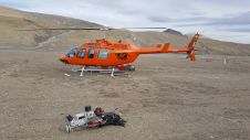
A multi-sensor, multi-temporal remote data collection campaign was conducted to monitor slope displacement and stability of the wedge during remediation work, to estimate the volume to be removed, to calculate the volumes of rock removed during scaling and blasting and to assess the rock joints and potential source zones where future failures might occur. Data collection consisted of an ALS survey of the region, oblique photogrammetry from a helicopter and boat, TLS and photographic monitoring of the unstable wedge during remediation work, total station monitoring of a location on the unstable wedge and multi-beam sonar data to map the underwater rock slope underlying the railway (Figures 2 and 3).
ALS and Oblique Photogrammetry
ALS data was collected from a helicopter covering a 4km2area along the rail line to obtain 3D data of a large area surrounding the rock slope failure. ALS data allows the mapping of discontinuity surfaces within the rock mass and identification of hazard source zones. The georeferenced accuracy of the ALS data in this study was in the 10cm range: too high to be used for monitoring slope displacements in this case.
ALS向下方向的方式收集数据, meaning that vertical rock slopes are occluded from the point cloud. To fill in the data gaps along the vertical rock slopes, and to obtain a photorealistic model of the slope surrounding the failure source zone, oblique photographs were taken from a helicopter and a boat. A total of 1,000 photos were taken, using a Nikon D800 camera equipped with a 35mm prime lens and camera-mounted GPS, from parallel lines looking perpendicular at the slope at various elevations. Photos were taken with greater than 60% overlap between photos and between passes, allowing for model construction using structure-from-motion software.
The camera-mounted GPS provided initial georeferencing and scale, but was later improved by fitting the constructed photogrammetry model to the ALS data using a scale-adjusting best-fit algorithm. Photos collected from the boat allowed for the construction of a more detailed model of the area directly surrounding the failure than the photos collected from the helicopter. The combined ALS and photogrammetric model allowed for better characterisation of the rock mass by reducing occlusion bias and provided a detailed photorealistic model of the slope surface surrounding the failure source zone.
TLS and Total Station, Photo Monitoring
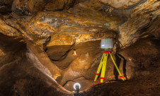
Monitoring with TLS commenced on 23 February 2015 using an Optech Ilris enhanced-range laser scanner at a frequency of 2 to 5 scans per day. Data was collected from two survey stations, one located 300m away from the rock slope at a bend in the track and the other across the lake, directly opposite the failure, at a distance of 1,000m.
TLS has the benefit of collecting millions of data points on the slope surface in a short period of time and can be used to detect 3D displacements when sequential datasets are compared. However, on average, it is limited to centimetre-range accuracy. For this reason a total station was used to monitor a single prism located at the base of the wedge with millimetre accuracy. Photographic modelling using high-resolution images was conducted twice per day for the purpose of monitoring the development of new surface cracks.
Collection and multi-temporal comparison of the TLS data provided a high-resolution point cloud of the failure area. When combined with the photogrammetric model, the data permitted the calculation of the volume of unstable rock to be removed. Sequential datasets were also analysed to monitor slope displacements, to identify any threat to remediation workers and to provide early warning of rock slope deformation.
Bathymetric Survey
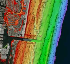
An initial multi-beam sonar survey of the rock slope under the railway line to the lake bottom was conducted on 17 February 2015. The primary purpose was to examine the rock slope directly beneath the railway line. Following completion of the scaling and blasting work, a second sonar survey was conducted on 10 March 2015 to permit detection of changes to the rock slope below the railway line as a result of the remediation efforts.
The combination of surface data and sonar data allowed changes above and below the water level (above and below the railway line) to be monitored. No significant deformation was detected with either TLS or the total station monitoring during the site remediation programme, giving confidence that the rock slope was stable. Figure 4 illustrates changes on the rock slope above and below the railway line as a result of the rock slide remediation and work to rebuild the railway line.
Multi-sensor Approach for Risk Management
As shown in this case, the use of multiple remote sensing technologies provides real-time data in a monitoring programme. The deployment of multiple technologies provides the full dataset needed for slope stability monitoring and assessment. Although ALS can provide 3D data for a wide area, it is downward looking and data gaps exist in vertical (oblique) surfaces. To fill in the gaps, photogrammetric models can be constructed from oblique photos taken from a helicopter or UAV. ALS and photogrammetric models can be compared on a multi-temporal basis providing information on slope change. However, these technologies lack the accuracy provided by terrestrial survey methods such as TLS and total station surveying. The latter techniques are required to obtain very detailed models of slopes and for monitoring small-scale slope deformation to provide warning of potential failure.
A multi-sensor approach is currently being investigated for other applications along the CN railway line. In general, ALS has provided data for identifying and delineating hazards over a larger area and has recently been used to monitor change. TLS has been used to characterise hazards at the slope scale, identify and monitor areas of deformation and quantify slope change. Photogrammetric models are constructed for sites where TLS collection is not possible and for rapid assessment of the extent of rock slope failure. Further research will focus on refining workflows, determining optimum data collection frequency and integrating space-borne remote sensing methods.
Further Reading
Lato, M. J., Hutchinson, D. J., Gauthier, D., Edwards, T. & Ondercin, M. (2014). Comparison of airborne laser scanning, terrestrial laser scanning, and terrestrial photogrammetry for mapping differential slope change in mountainous terrain.Canadian Geotechnical Journal, 52(2), 129-140.
Kromer, R. A., Hutchinson, D. J., Lato, M. J., Gauthier, D. & Edwards, T. (2015). Identifying Rock Slope Failure Precursors Using LiDAR for Transportation Corridor Hazard Management.Engineering Geology.
The Authors
Ryan Kromer
瑞安krom女王想博士生ty, Canada, working in collaboration with the University of Lausanne, Switzerland. Ryan previously obtained his Bachelor in Geological Engineering from Queen’s University in 2010. He has worked professionally as a project manager for various geotechnical projects including design of bridge foundations, tunnel projects and rockfall hazard assessments along transporting corridors. A primary element of his current research includes monitoring rock slopes along transportation corridors using modern remote sensing technologies.
Dr Jean Hutchinson
Dr Hutchinson is a professor and department head for Geological Sciences and Geological Engineering at Queen’s University. Jean obtained degrees in GeoEngineering from the University of Toronto in 1984, Geotechnical Engineering from the University of Alberta in 1988 and Rock Engineering from the University of Toronto in 1992. Her research areas include work on engineering geology risk assessment, natural hazards and landslides, mining-induced ground subsidence, underground rock support design, in-situ and remote sensing techniques for assessing ground conditions, and engineering education.
马特博士Lato
Dr Lato obtained a BSc in Geological Engineering (2006) and a PhD Eng in Geotechnical Engineering (2010) from Queen’s University. He has a diverse background in the field of geotechnical applications of 3D remote sensing technologies, specifically Lidar and photogrammetry. He has been involved in projects in Canada, Europe, South America and Australia. He has worked on various projects including tunnelling (drill and blast and TBM excavation), mining (open pit and underground) and slopes along transportation corridors. His direct field of expertise is in the application of Lidar and photogrammetry for geotechnical mapping and change-detection monitoring and stability assessment.
Tom Edwards
Tom is the senior geotechnical engineer with Canadian National Railways and is the co-chairman of the Railway Ground Hazards Research Program. He is a geological engineer from the University of Manitoba and has been with Canadian National Railways for 39 years. In the position of senior geotechnical engineer, he is currently responsible for evaluating and mitigating ground hazards affecting the railway across Western Canada.
Figures
Figure 1, CN railway line at Seton Lake, British Columbia. On 9 February 2015 a rockslide occurred, exposing an overhanging, unstable rock wedge.
Figure 2, Multi-sensor data collection – TLS and total station monitoring of failure area, ALS survey of 4km2area and helicopter and boat-based photogrammetry of the surrounding mountain.
Figure 3, Outline of data collected. The yellow star marks the failure location.
Figure 4, Change detection of the slope above and below water level, due to blasting on the slope and construction work on the railway line, using multi-sensor monitoring.
Make your inbox more interesting.Add some geo.
Keep abreast of news, developments and technological advancement in the geomatics industry.
Sign up for free


